 Yesterday, I spent my spare time on creating a camera calibration for our bean sorter project. The purpose of the calibration is to convert measurements of beans in captured images from pixel units to mm units. Images are made up of pixels, so when measurements are performed we know how big things are in terms of pixels. Something might be 20 pixels wide and 17.7 pixels high (subpixel calculations is a topic for another day). Knowing the width of something in an image is pretty worthless because the real world width ( e.g. in millimeters) of that object will vary greatly based on magnification, camera angle and a bunch of other stuff. That is a big problem if the camera moves around a lot.
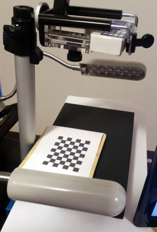
Fortunately, in our case, the camera will be in a fixed location and the distance to the falling beans will always be the same. That allows us to make some fixed calculations to convert pixel units to millimeters. To that end, we put a “calibration target” in the cameras field of view at the  position where through which the beans will fall. In our case that calibration target is a checkerboard pattern with squares of a known size. If we take a picture of the checkerboard pattern, then find the location of each square in the image in pixels, and store that information away.
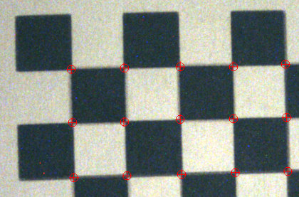
Notice the red marks at each intersection of squares in the checkerboard–those are the found pixel positions (e.g. 133.73 pixels from the top of the image and 214.5 pixels from the left edge of the image). We can then convert the positions and sizes of found beans in the image from pixel units to mm units by using equations derived from the know mm sizes of the squares and the found position of the squares in the image as measured in pixel units. I used to have to hand write the equations to do this, but now there are open source libraries for this, so I was able to do the whole thing in an evening.

Gene Conrad
Does this also take care of paralax? or is that minimal in this case?
Yes it does. In this case, because we don’t need extreme accuracy, I am using a pretty basic transform. If it turns out we need more accuracy, we can switch to piece-wise linear or cubic interpolation based calibration or we can do a full blown characterization of the optical system and make that part of the calibration. I do not think that will be necessary.